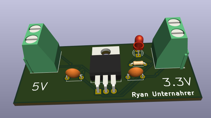
I have always had an interest in electronics since my Grandfather introduced the hobby to me. But over the past few years, I haven’t been as active as I once was. After a night of YouTube browsing, I found myself drawn back in and decided to teach myself Print Circuit Board (PCB) Design. This stuff is different from my normal work in the software world but is an interesting learning opportunity.
Introduction
After some research and experimentation, I decided to use the open-source software package KiCAD for my design of circuits and PCBs. I found KiCAD to have numerous resources online. It is a fully featured package for circuit and PCB design that includes symbol and footprint editors. I learnt most of the basics from this video on YouTube but the forums are very active and helpful if you have specific questions.
The Circuit

After some time learning about the software, I decided to create a simple circuit for fabrication. Many standard power supply methods for microcontrollers use 5V. On the other hand, my Raspberry Pi Pico and many of its components use 3.3V. So I decided to create a voltage regulator.
The main component of this is the LM1117 specifically the 3.3 variant. This takes an input voltage of 1.2 to 13.8V input and outputs 3.3V. Texas Instruments also recommends a 10uF capacitor to improve the consistency of power and reduce any noise in the circuit. So I placed one of these each on the input and output. I also added an indicator LED on the output.
I/O
For input and output, I had to decide how I would input and output power from the device. The three main options I considered were pins/sockets, soldered connections, and screw terminals.
Pins and sockets are both commonly used in the world of microcontrollers and are well-suited to hobbyist and prototyping projects. They are also the IO method for many of my microcontrollers and components. However, they lack the durability and stability needed for use in more permanent projects.
Soldered connections are the most permanent and cost-effective option. But their permanence is also their biggest drawback. For a hobbyist like myself constantly having to resolder these to each project will quickly become a hassle as I jump from project to project, prototype to prototype.
The final option was screw terminals. They are the most expensive option, the ones I am using are $1.90 each, but they strike a balance between the permanence of soldered connections and the ease of change in pins. Therefore I decided to use screw terminals for this project.
Layout

After I designed the circuit and chose the components that would be used I imported the footprints into the PCB layout software that is a part of KiCad. I decided to use a 2-layer PCB as it provides flexibility in layout. I ended up making use of this to allow traces to cross one another.
Fabrication

For fabrication, I decided to use JLC PCB as they are both cheap and seem to have a good reputation among hobbyists. For this, I had to generate Gerber and Drill files for them. I found KiCAD made this very easy and after uploading the files and setting a few options my PCBs were ordered. In total including shipping, this cost me only $5.67 which I consider an exceedingly reasonable price for 5 PCBs printed and shipped when working on this small of an order size.
Conclusion
To conclude, I have found this project to be one of the most engaging side projects I have done in recent times. It has greatly boosted my confidence in electronics. I have learnt a great many new skills and I hope to learn more soon. I will post an update when I receive the boards going through my assembly and testing of the boards.

